Grand Willys Project
-
Gojeep

- Old Hand
- Posts: 7221
- Joined: Mon Jan 07, 2008 1:24 pm
- Location: Eastern Suburbs of Melbourne
- Contact:
Re: Grand Willys Project
Cool. Our favourite national park in the whole country is Karijini. Be a good excuse to go back there. 
Marcus
To try where there is little hope, is to risk failure.
Not to try at all, is to guarantee it!
____| \______\
|/¯\ |¯ |----O||||O
()_)-o-)¯¯()_)-o-)_)
To try where there is little hope, is to risk failure.
Not to try at all, is to guarantee it!
____| \______\
|/¯\ |¯ |----O||||O
()_)-o-)¯¯()_)-o-)_)
-
Gojeep
- Old Hand
- Posts: 7221
- Joined: Mon Jan 07, 2008 1:24 pm
- Location: Eastern Suburbs of Melbourne
- Contact:
Re: Grand Willys Project
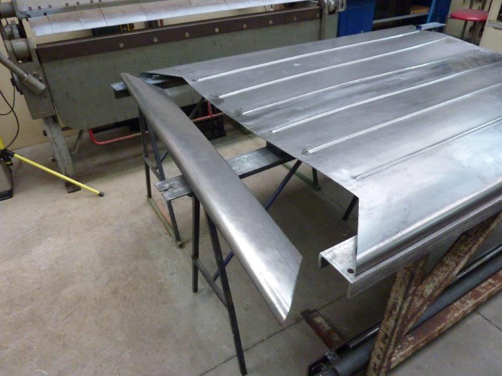
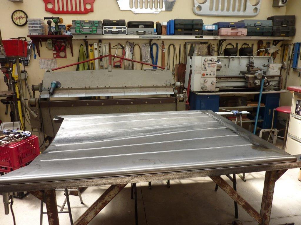
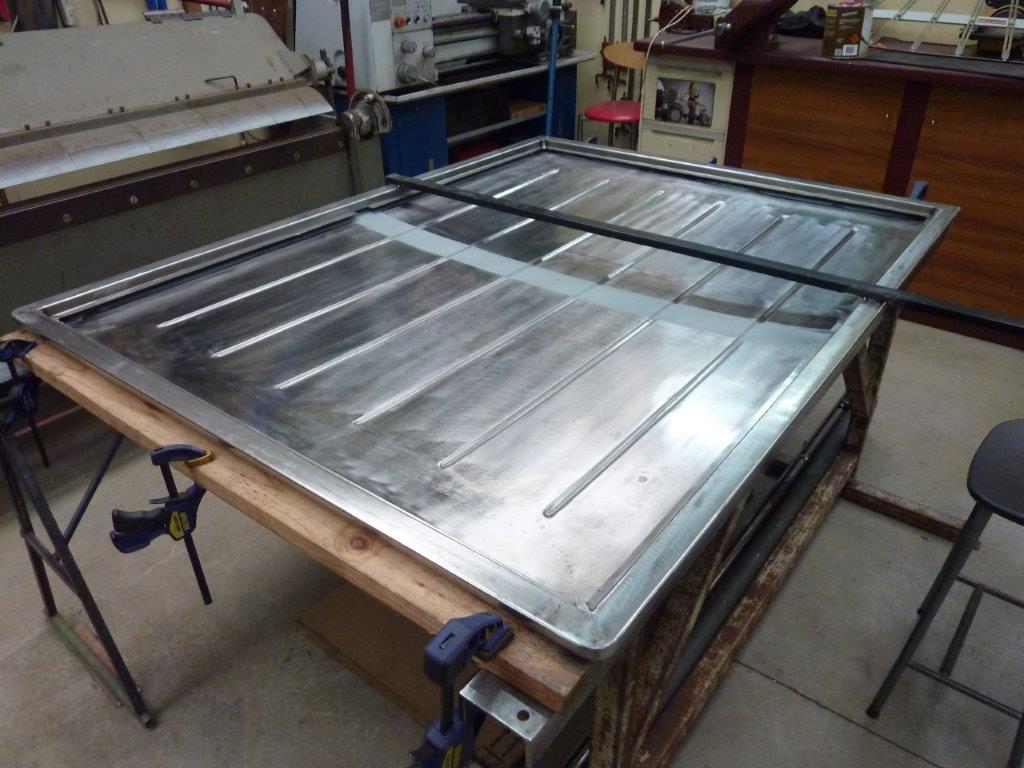
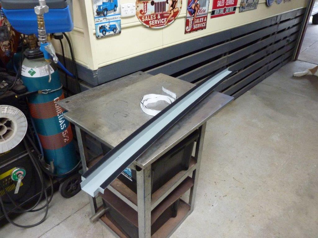
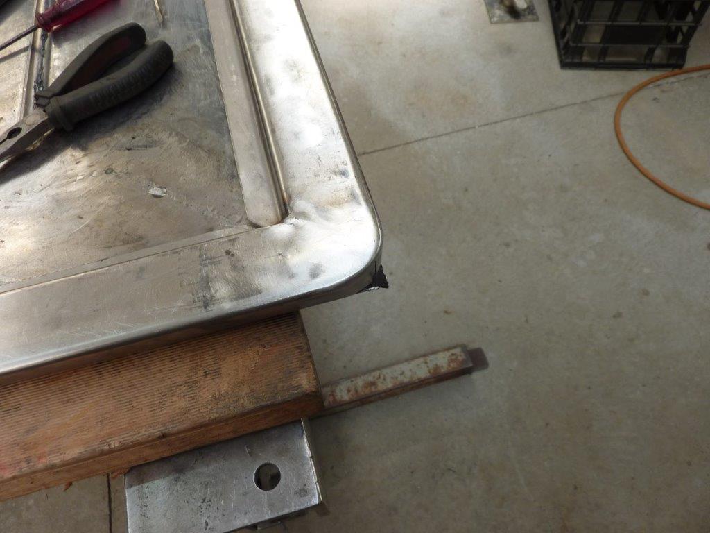
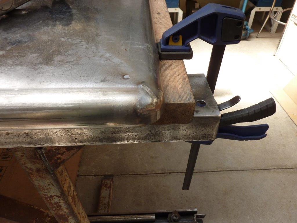
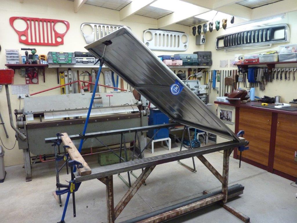
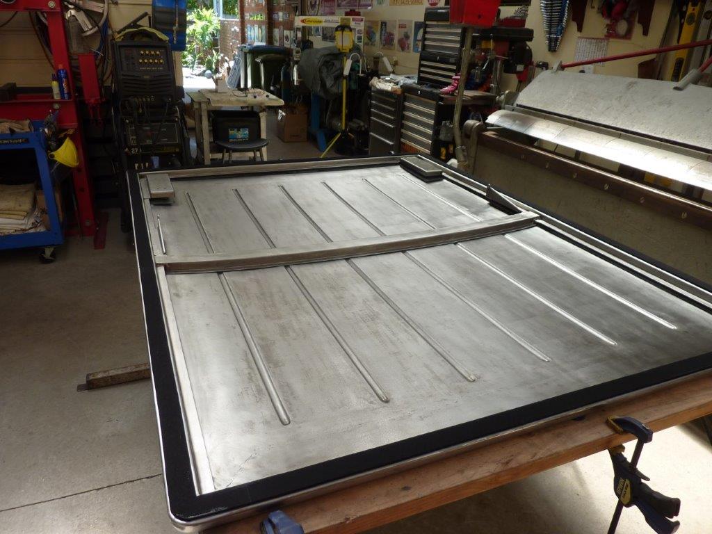
Time to add the ends for the hard tonneau cover.
Test fit showed it should work out well enough.
Turned the cover upside down so I could jack the cover to the right width. The cover sagged after the end was cut away and lost all its support.
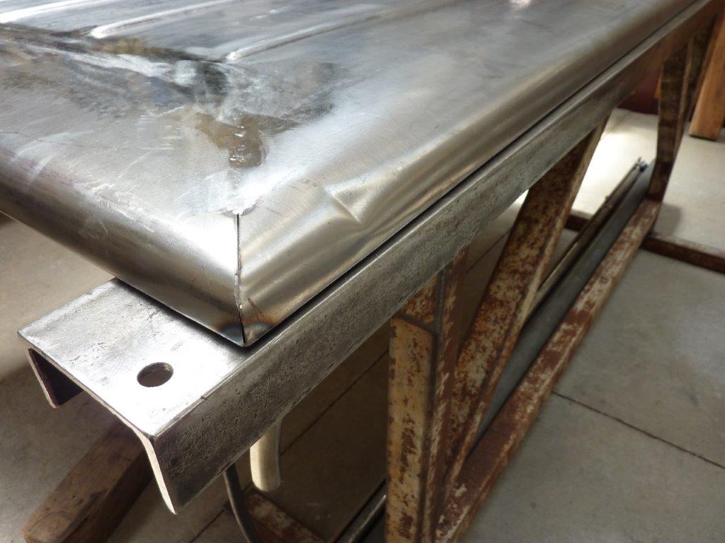
I marked the exact centre of both pieces and made sure those lines matched before tack welding. One tack at a time and then stretching it to keep things in alignment before the next tack, otherwise it will overlap itself with the shrinkage.
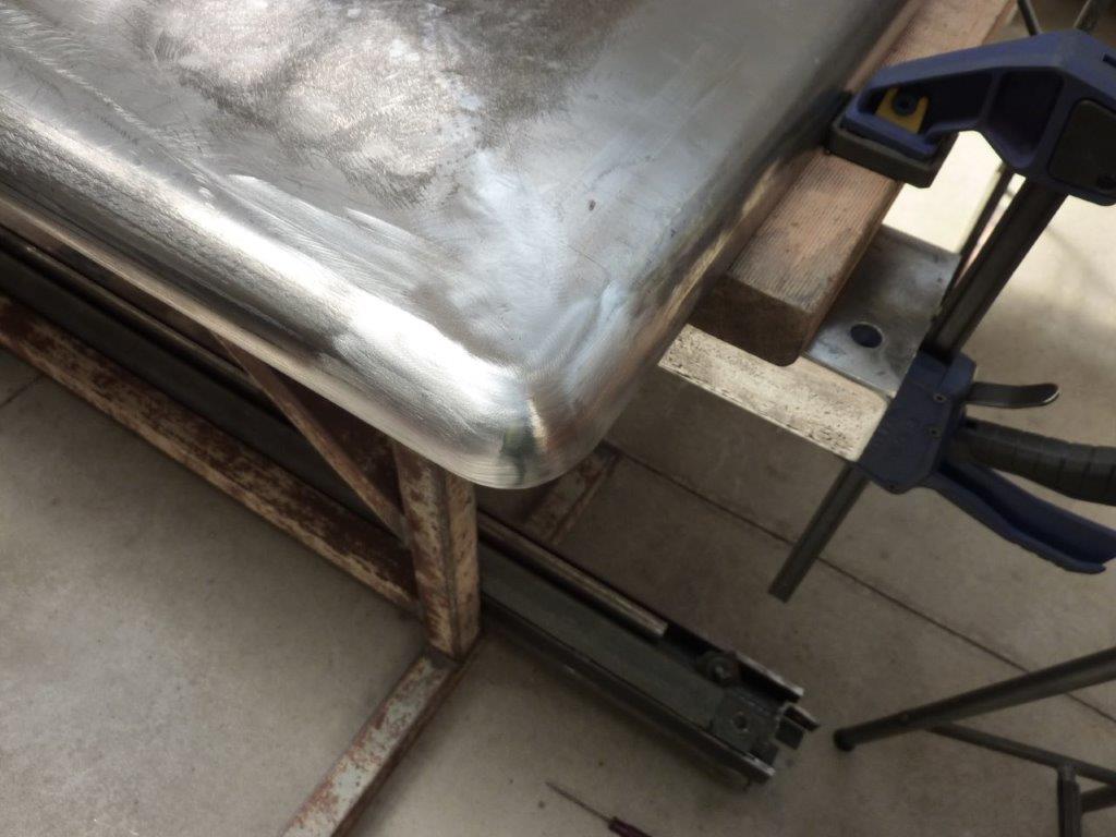
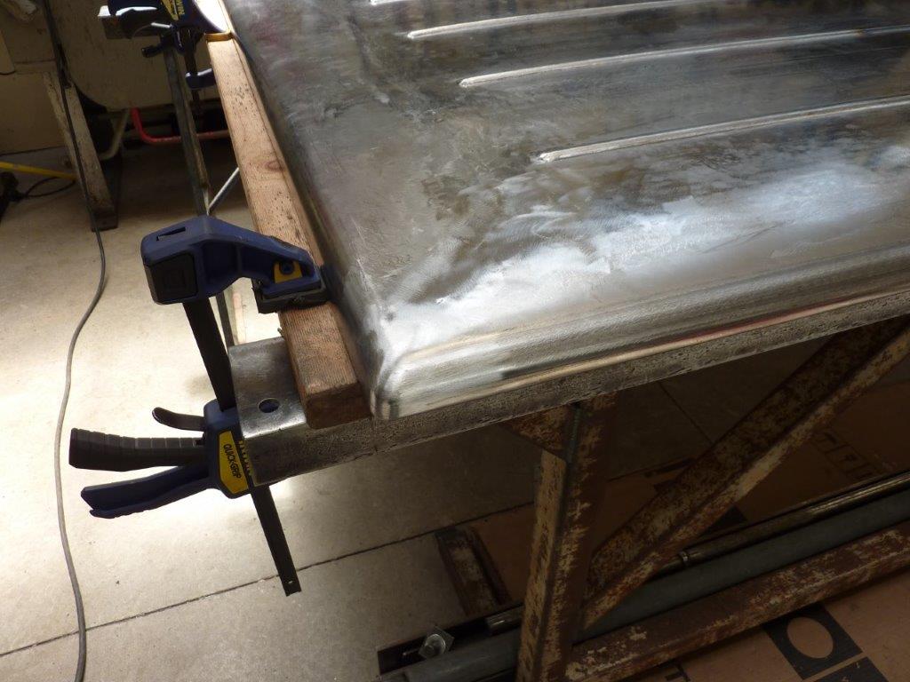
Can see how much support the end gives!
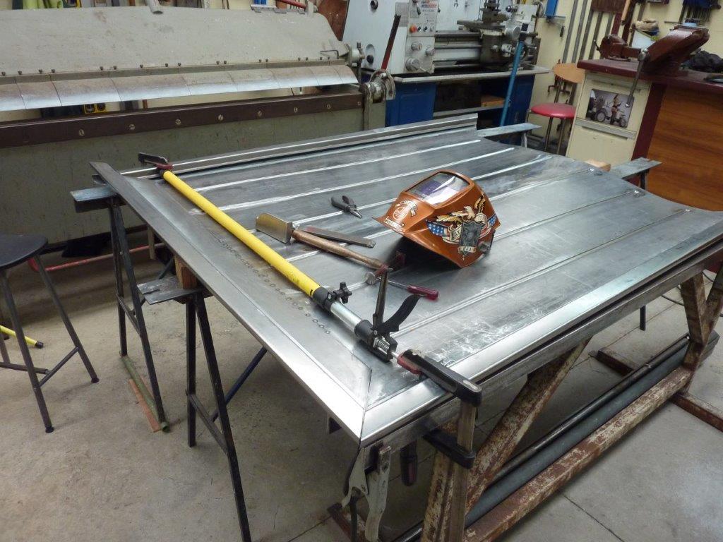
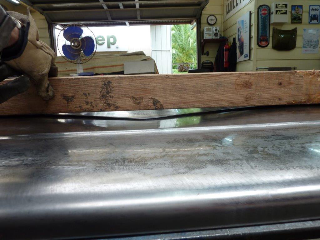
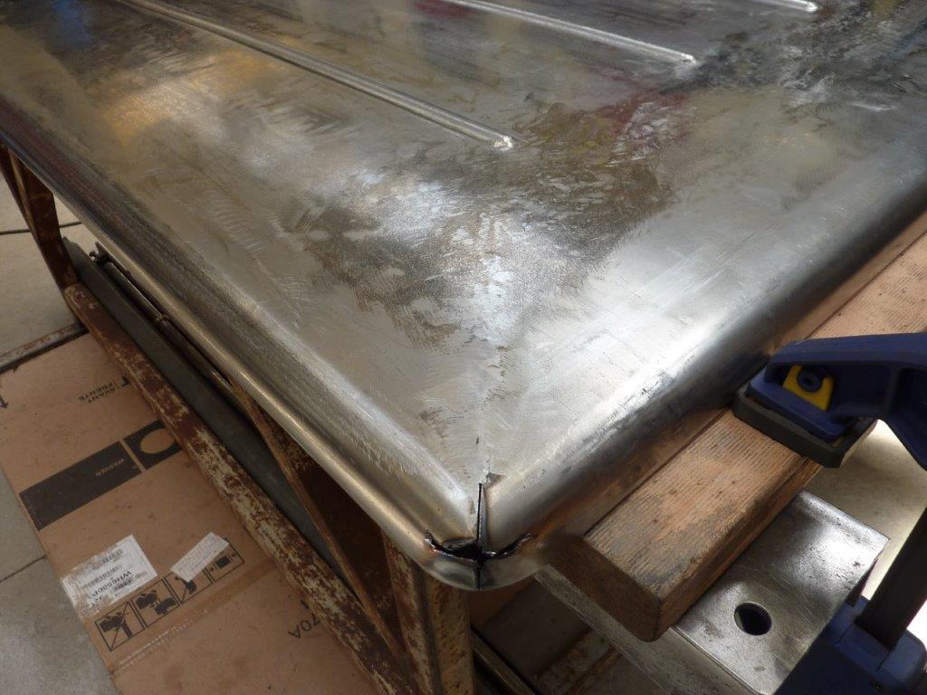
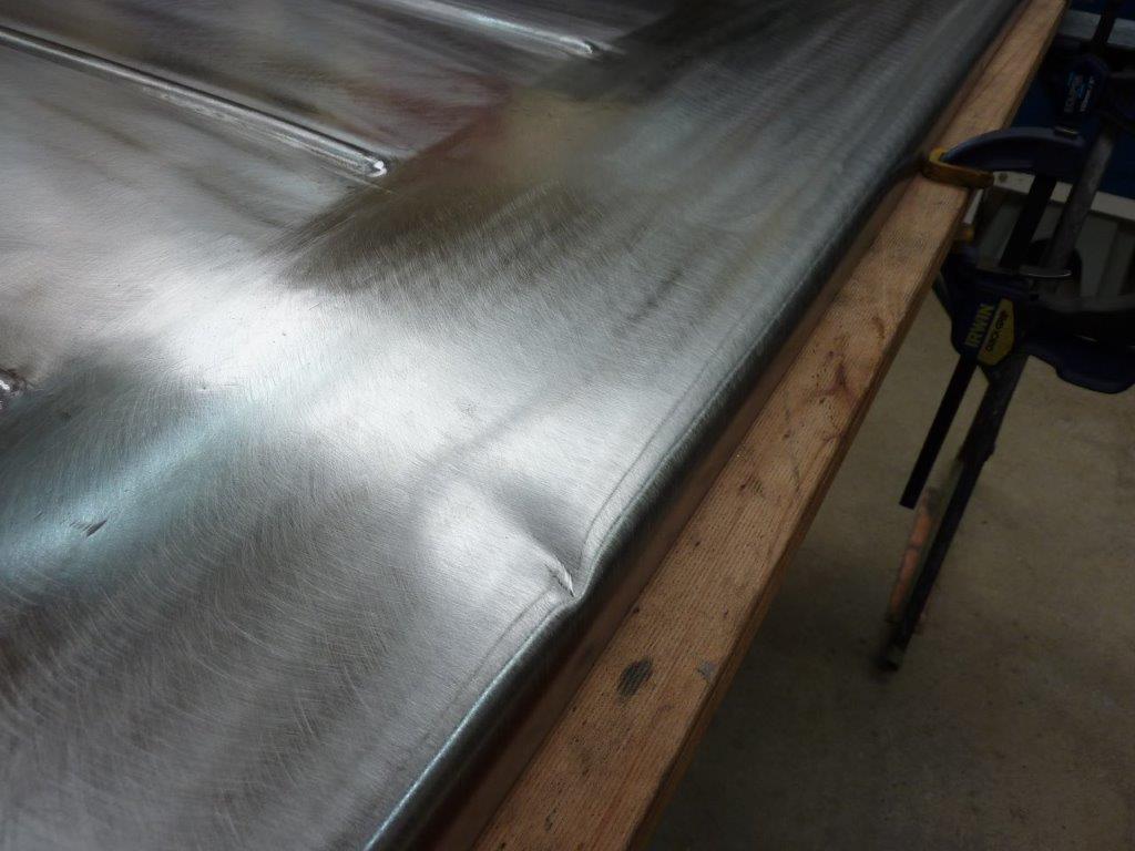
I had the cover upside and was planishing away and did not notice this side was moving. It fell off the trestle straight down on to the support legs!
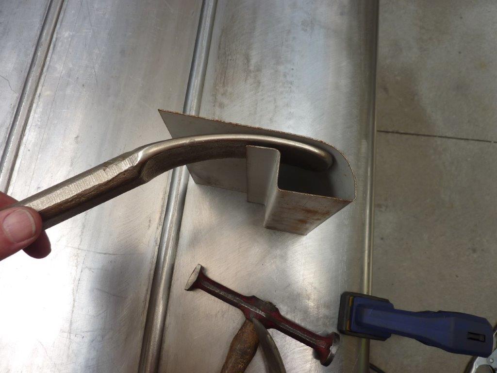
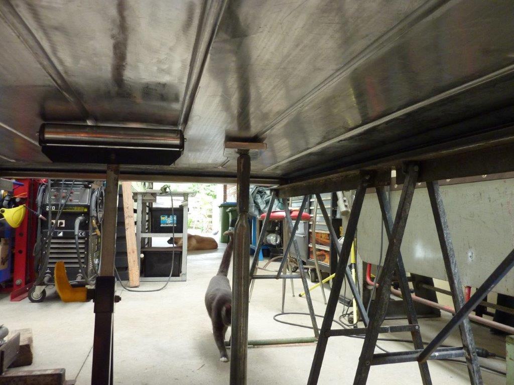
This gives you an idea of how I have to work inside the cover behind where the dent is using one of my spoons.
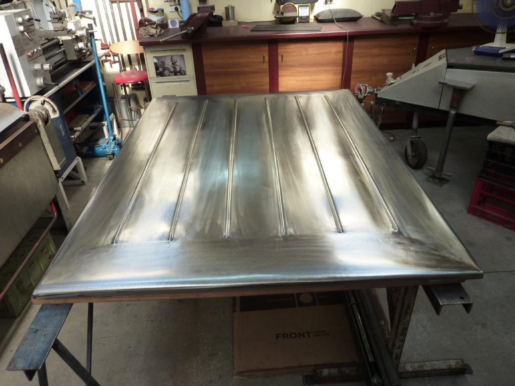
I did it like paintless dent removal where you massage the back of the dent and lightly tap around the edge of it from the outside. Came out pretty well considering how sharp the crease was.
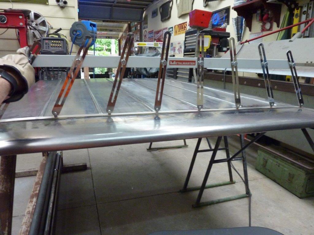
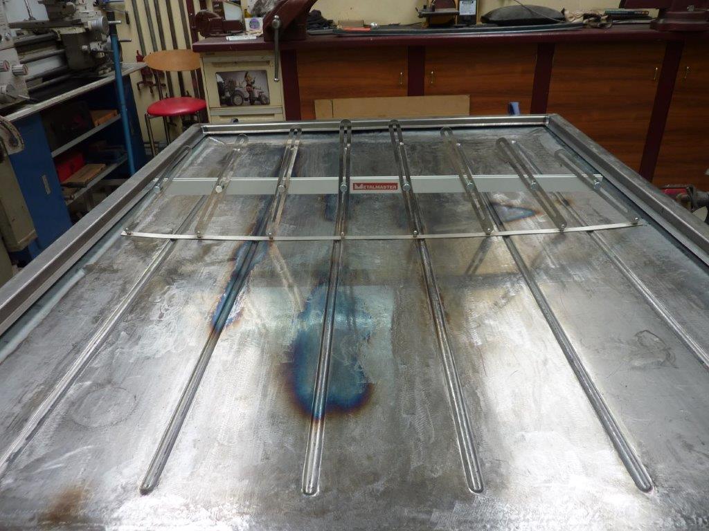
Also going around using my large profile gauge to make sure it is identical left to right and end to end etc. If you spin it 180* and you have a gap under it like shown, it needs to be altered. Stretching up the left side made it the same in this case.
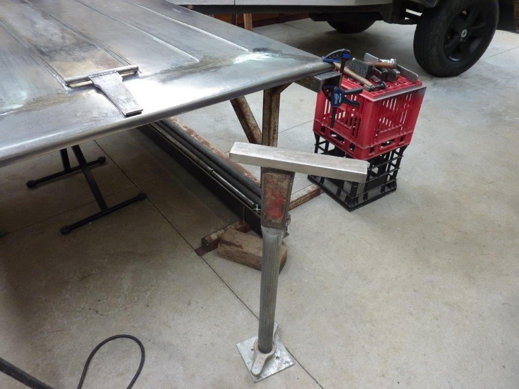
I made up this adjustable stake stand using the bottom of a scaffolding tower leg. This will help my back in the hard to reach places.
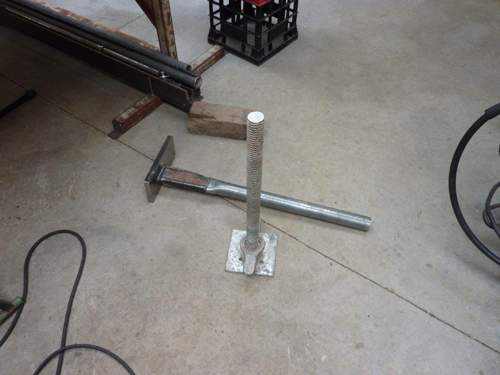
Nearly all my homemade stakes will fit into it including the die that matches the ribs etc.
The adjustment is great as the cover has different heights due to the crown as you move left to right, front to rear etc. Just wind it up or down to suit.
Marcus
To try where there is little hope, is to risk failure.
Not to try at all, is to guarantee it!
____| \______\
|/¯\ |¯ |----O||||O
()_)-o-)¯¯()_)-o-)_)
To try where there is little hope, is to risk failure.
Not to try at all, is to guarantee it!
____| \______\
|/¯\ |¯ |----O||||O
()_)-o-)¯¯()_)-o-)_)
-
Mudgy
- Old Hand
- Posts: 3249
- Joined: Sun Dec 12, 2010 8:36 am
- Location: Gosford, NSW
Re: Grand Willys Project
Fantastic work, mate. I bet the neighbours heard a few choice words from your garage when you saw those dents !
Cheers, Mudgy
Cheers, Mudgy
Good Judgement comes from experience....experience comes from bad judgement.
-
Gojeep
- Old Hand
- Posts: 7221
- Joined: Mon Jan 07, 2008 1:24 pm
- Location: Eastern Suburbs of Melbourne
- Contact:
Re: Grand Willys Project
Ha ha, you would think. But thought, O'well, lets see if I can get it out before worrying about it.Mudgy wrote:Fantastic work, mate. I bet the neighbours heard a few choice words from your garage when you saw those dents !
Cheers, Mudgy
Marcus
To try where there is little hope, is to risk failure.
Not to try at all, is to guarantee it!
____| \______\
|/¯\ |¯ |----O||||O
()_)-o-)¯¯()_)-o-)_)
To try where there is little hope, is to risk failure.
Not to try at all, is to guarantee it!
____| \______\
|/¯\ |¯ |----O||||O
()_)-o-)¯¯()_)-o-)_)
-
Gojeep
- Old Hand
- Posts: 7221
- Joined: Mon Jan 07, 2008 1:24 pm
- Location: Eastern Suburbs of Melbourne
- Contact:
Re: Grand Willys Project
I noticed that a couple of the ribs were higher than they should be. This one was the worst at about 5mm-5/16". So I was heating it with a torch to a blue colour and suddenly it collapsed down in front of where I was heating. I think I was trying to heat too long a section at once. I used a bar dolly that matched the rib under it to knock it back up to level again before continuing on.
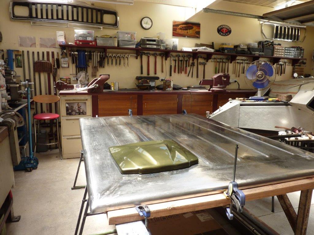
Laid my paint colour sample on it to give me some inspiration to keep at it.
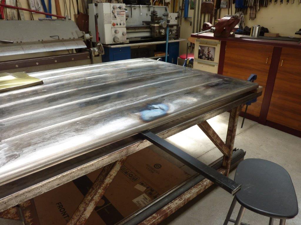
I noticed the side started bending inwards and upwards as well. Fortunately lowering the crown spread it back to where it was straight again, but caused the top of the skin to collapse! I tried the technique of hitting it down while it was hot, but it caused a lot of damage for me. I obviously need to be better at it. Went back to heating and letting it cool naturally which leaves the panel really tight in the area. I then hit it down off dolly or onto a lead filled rubber block to lower the high spot.
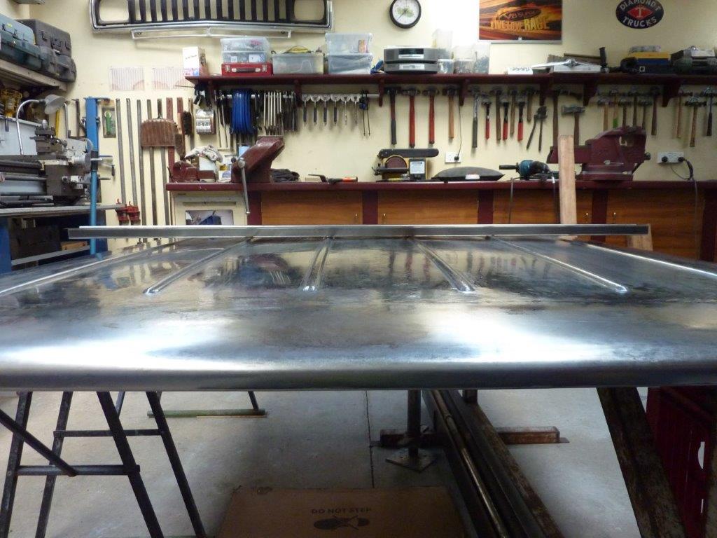
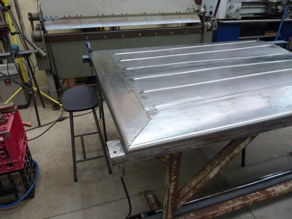
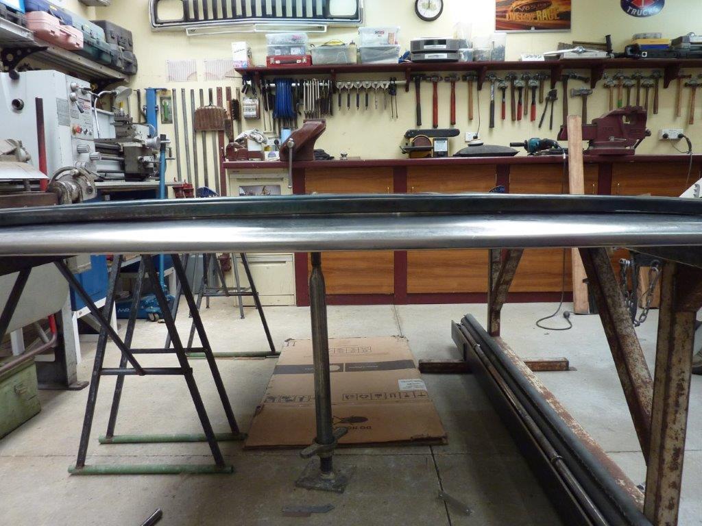
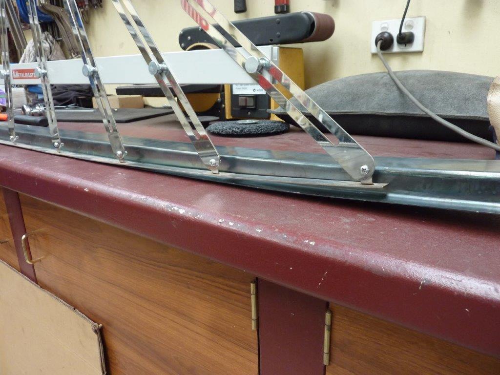
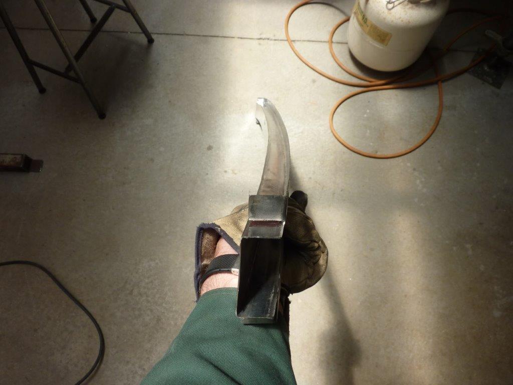
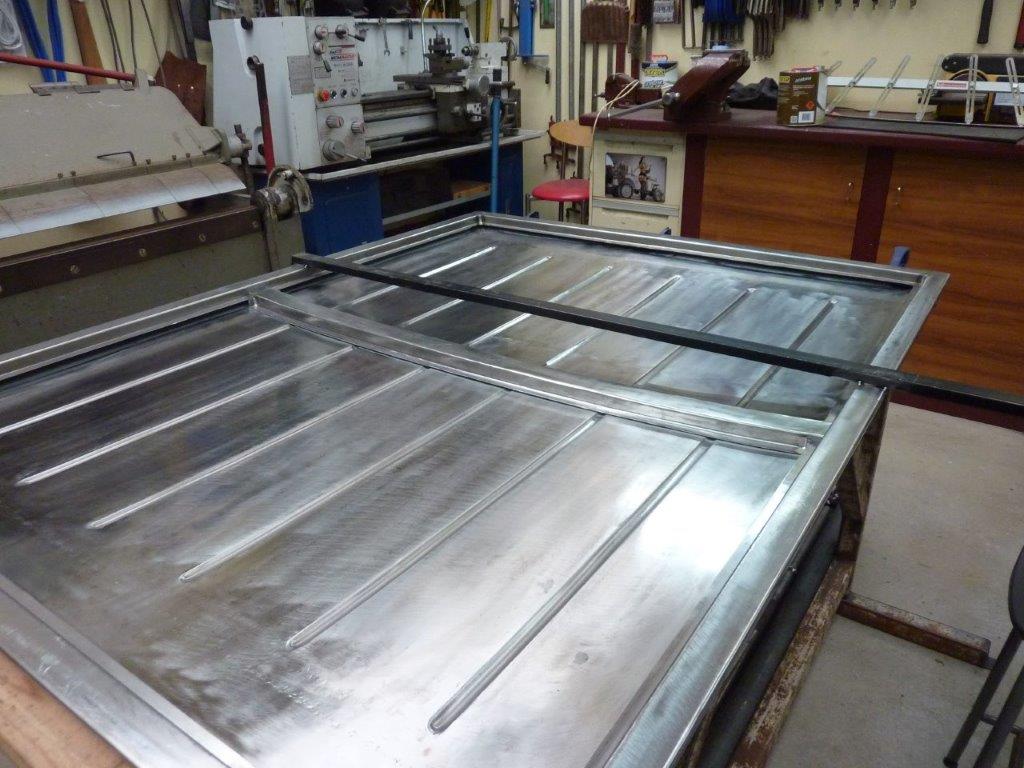
Once the crown was checked with the profile gauge left to right, front to rear, I could then make a centre crossmember. I folded up this hat channel and can see how much it needs to bend.
It starts out perfectly straight but needs a gradual curve to it to match the crown on the panel.
Using a propane torch I slowly just heated the top of it and let it cool naturally. Showing some good progress already.
Can see the ends are about halfway closer now.
The curve needs to be more than the panel below it like it is already starting to show. One because there is more crown in the middle, but also it is the top surface of the crossmember that has to match.
Time to take an accurate profile of where the crossmember will sit.
Can see it still has a little more to go. I tried the partial cut and weld back up method, but it was too harsh for such a gradual curve. So had to cut it and put it back to what it was.
The torch method was not getting it any further so actually placed a weld bead on the top edge where I needed to add the extra curve. The weld causes it to shrink and add more curve. Could place it in slightly different places left to right to get the curve perfectly even as well this way and was only needed near the ends where it was much steeper.
Prepping the area ready for the crossmember to go in. I left the brace in place to make sure the flanges didn't twist during welding or pull together.
Here is a trick I picked up from Rod Covell from his old Street Rodder column where someone had said they had a problem with the adhesive between the roof panel and crossmember showing up in the reflections of their polished paintwork depending on the temperature of the day. Manufacturer's use this method on boots and bonnets etc, but the blobs of adhesive are quite thick and the frame is a good 5mm-5/16" away from the skin to help with the movement. So he said that he uses the loop/soft side of Velcro as a cushion to protect the paint from rubbing and to stop it rattling. I have used it with success on my roof crossmember as well.
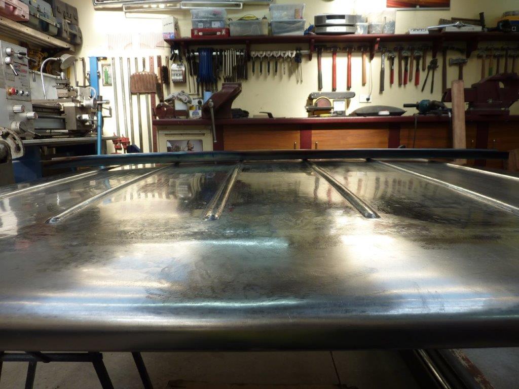
Crossmember dropped into place ready for welding.
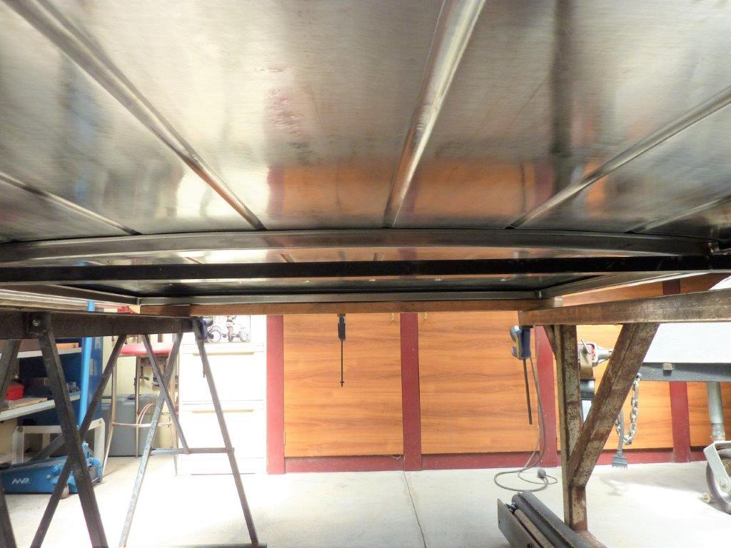
Follows the crown nicely.
Marcus
To try where there is little hope, is to risk failure.
Not to try at all, is to guarantee it!
____| \______\
|/¯\ |¯ |----O||||O
()_)-o-)¯¯()_)-o-)_)
To try where there is little hope, is to risk failure.
Not to try at all, is to guarantee it!
____| \______\
|/¯\ |¯ |----O||||O
()_)-o-)¯¯()_)-o-)_)
-
Gojeep
- Old Hand
- Posts: 7221
- Joined: Mon Jan 07, 2008 1:24 pm
- Location: Eastern Suburbs of Melbourne
- Contact:
Re: Grand Willys Project
Great seeing the forum back so updating the thread.
Marcus
To try where there is little hope, is to risk failure.
Not to try at all, is to guarantee it!
____| \______\
|/¯\ |¯ |----O||||O
()_)-o-)¯¯()_)-o-)_)
To try where there is little hope, is to risk failure.
Not to try at all, is to guarantee it!
____| \______\
|/¯\ |¯ |----O||||O
()_)-o-)¯¯()_)-o-)_)
-
Gojeep
- Old Hand
- Posts: 7221
- Joined: Mon Jan 07, 2008 1:24 pm
- Location: Eastern Suburbs of Melbourne
- Contact:
Re: Grand Willys Project
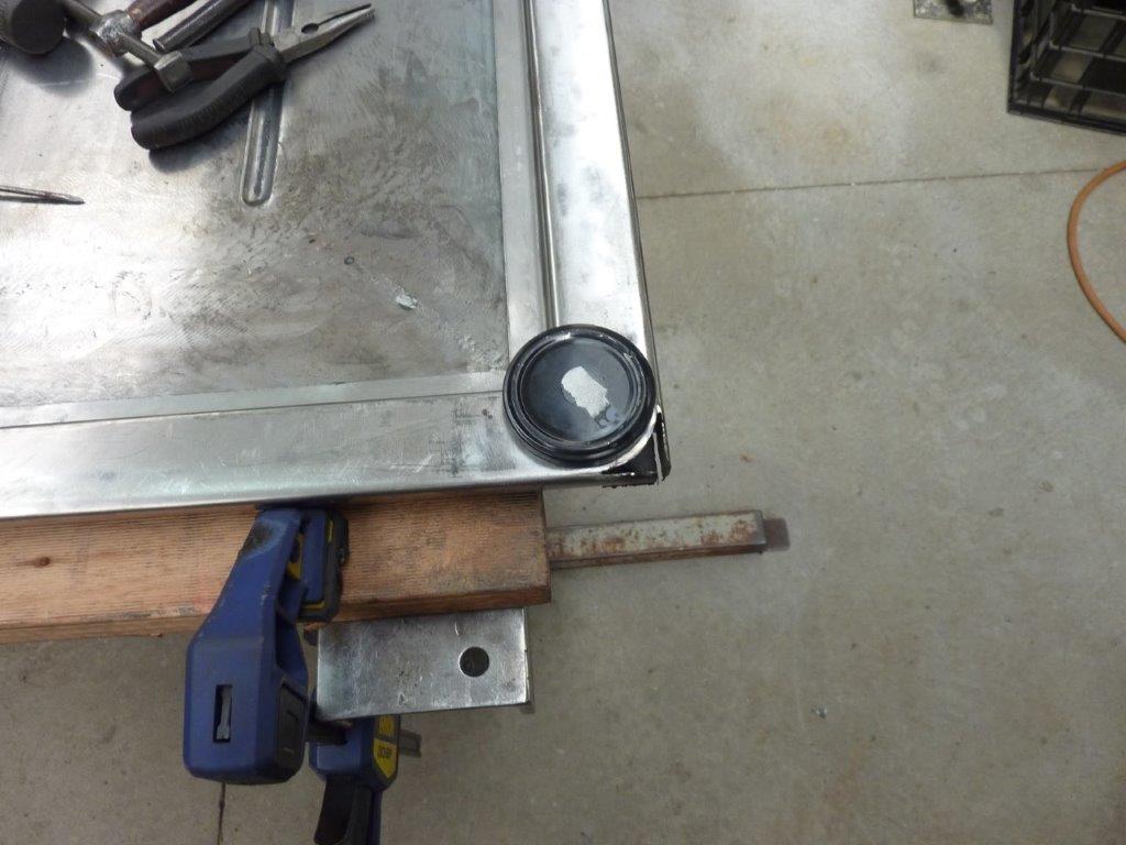
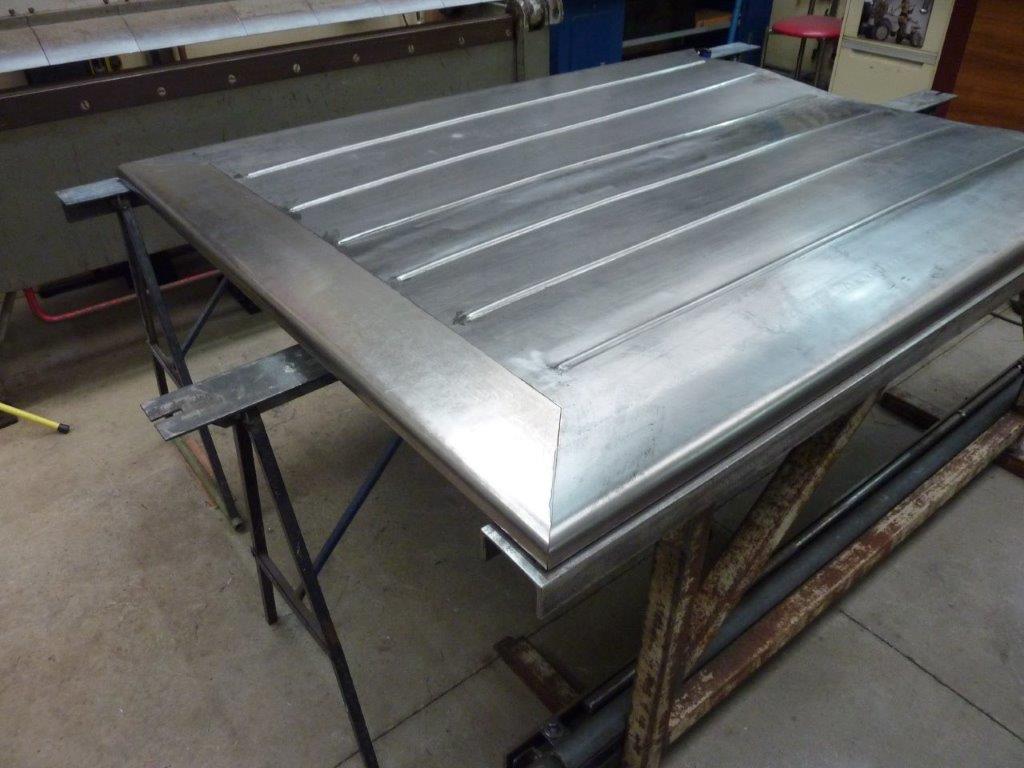
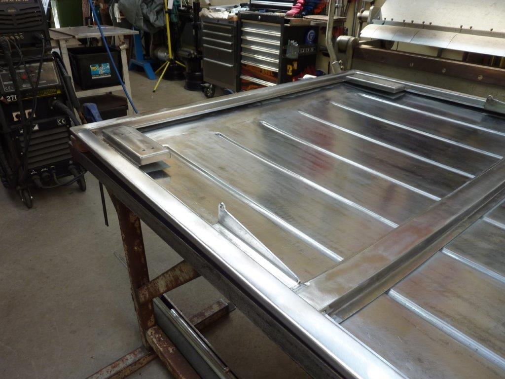
I never wanted the sharp corners on the cover which is why they were never welded. The plan was always to radius the tailgate end of the cover to be proportional to the radius at the end of the bedsides. The jam lid was just the right size and you can see how I have cut away the underside of the cover to match it and slot the vertical part of the sides.
I pulled the vertical parts around to follow the base.
From the top I could then make adjustments to the radius of the vertical part before bring the top down to meet it.
I slowly cutting a triangle out of each side of the very top part and tapped it down to give it a radius rather than a ridge.
Once it rolled over the curve I could weld it shut.
Ground it down to almost flush.
Then finished off with a flap disc.
At the cab end of the cover I just matched the radius to that of the ribs, as the bedsides are squared off at that end.
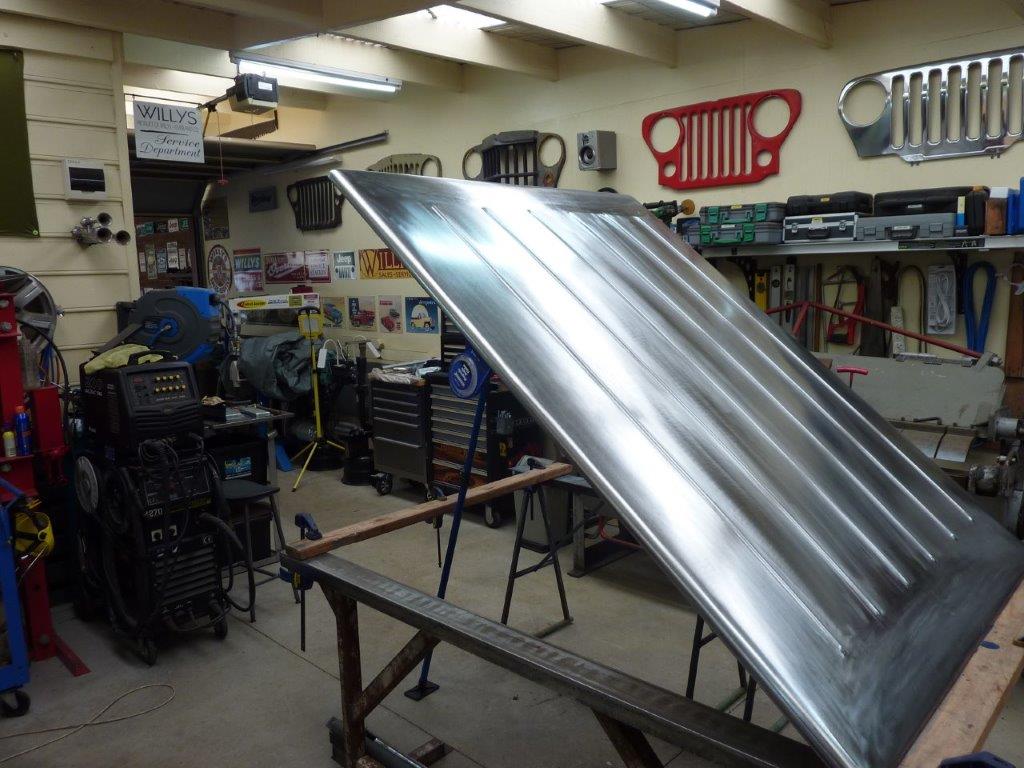
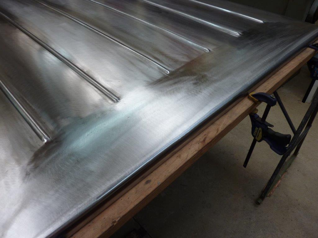
Every time I had been waiting for heat shrinks to cool, I was lifting the little low spots and planishing down the high ones. The final sand was just to remove the heat discolouration and most of the shrinking disc marks. I then followed with a 7" strip disc. I'm pleased with the way it has turned out and is exactly how I imagined it.
Marcus
To try where there is little hope, is to risk failure.
Not to try at all, is to guarantee it!
____| \______\
|/¯\ |¯ |----O||||O
()_)-o-)¯¯()_)-o-)_)
To try where there is little hope, is to risk failure.
Not to try at all, is to guarantee it!
____| \______\
|/¯\ |¯ |----O||||O
()_)-o-)¯¯()_)-o-)_)
-
Gojeep
- Old Hand
- Posts: 7221
- Joined: Mon Jan 07, 2008 1:24 pm
- Location: Eastern Suburbs of Melbourne
- Contact:
Re: Grand Willys Project
Video update on building the hard cover for the Willys from scratch.
Marcus
To try where there is little hope, is to risk failure.
Not to try at all, is to guarantee it!
____| \______\
|/¯\ |¯ |----O||||O
()_)-o-)¯¯()_)-o-)_)
To try where there is little hope, is to risk failure.
Not to try at all, is to guarantee it!
____| \______\
|/¯\ |¯ |----O||||O
()_)-o-)¯¯()_)-o-)_)
-
Gojeep
- Old Hand
- Posts: 7221
- Joined: Mon Jan 07, 2008 1:24 pm
- Location: Eastern Suburbs of Melbourne
- Contact:
Re: Grand Willys Project
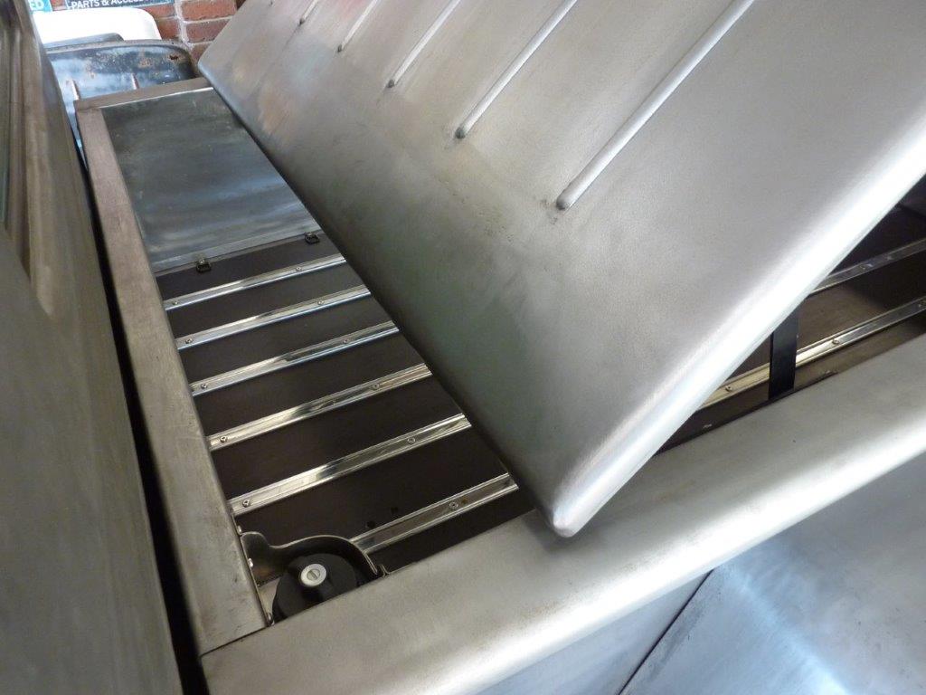
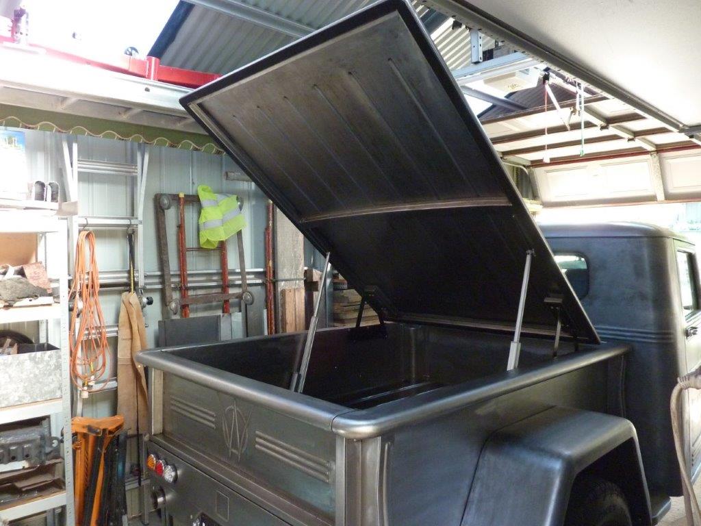
Working out how high we want it to raise. We settled on 40*.
40* should give us plenty of room around the hinge area to still get things in and out.
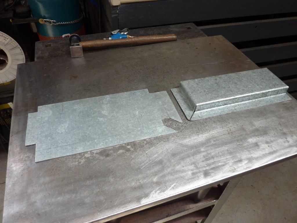
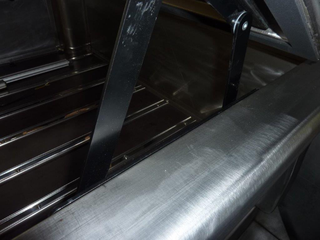
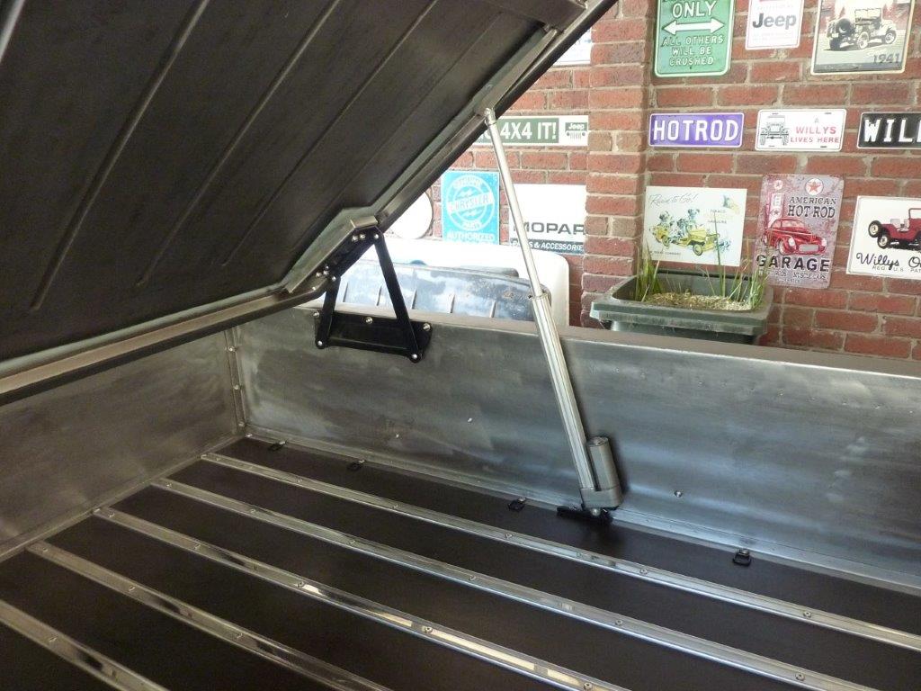
Making support mounts for the hinges to bolt too. The weird arrow shape is what you need if you have a step down and a flange and want it to fully meet in the corner.

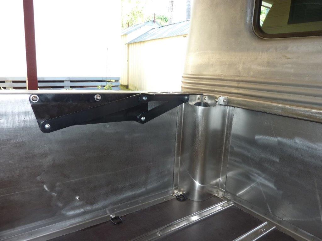
I had been looking for some time to find a hinge like this that was a stronger version of a sofa bed hinge where it lifts up and back at the same time.
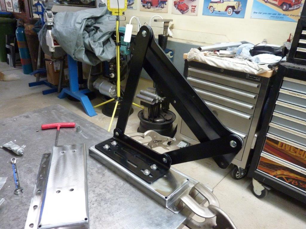
Upside down to the way it will mount, but you get the idea of how the pivot point raises and moves backwards
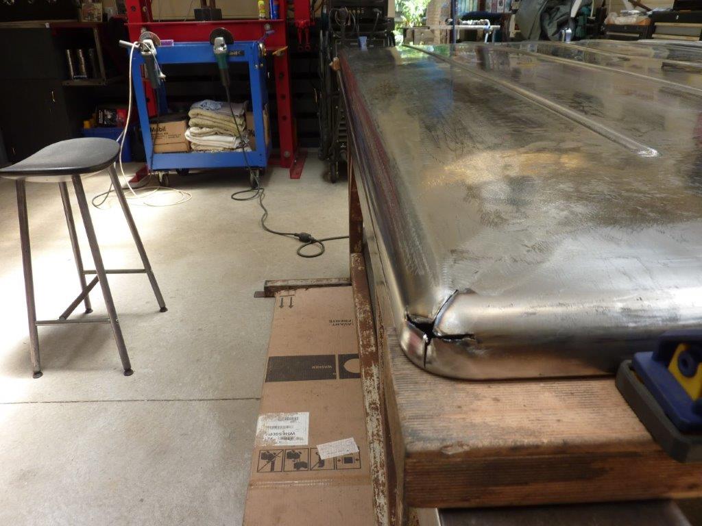
Well third time unlucky? Is that a thing? Turning it over to fit the new hinge mounts and it slipped right off the trestle again and put an even sharper dent this time on the new end piece.
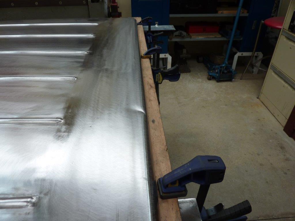
Hurts more as thought I was done with the panel work!
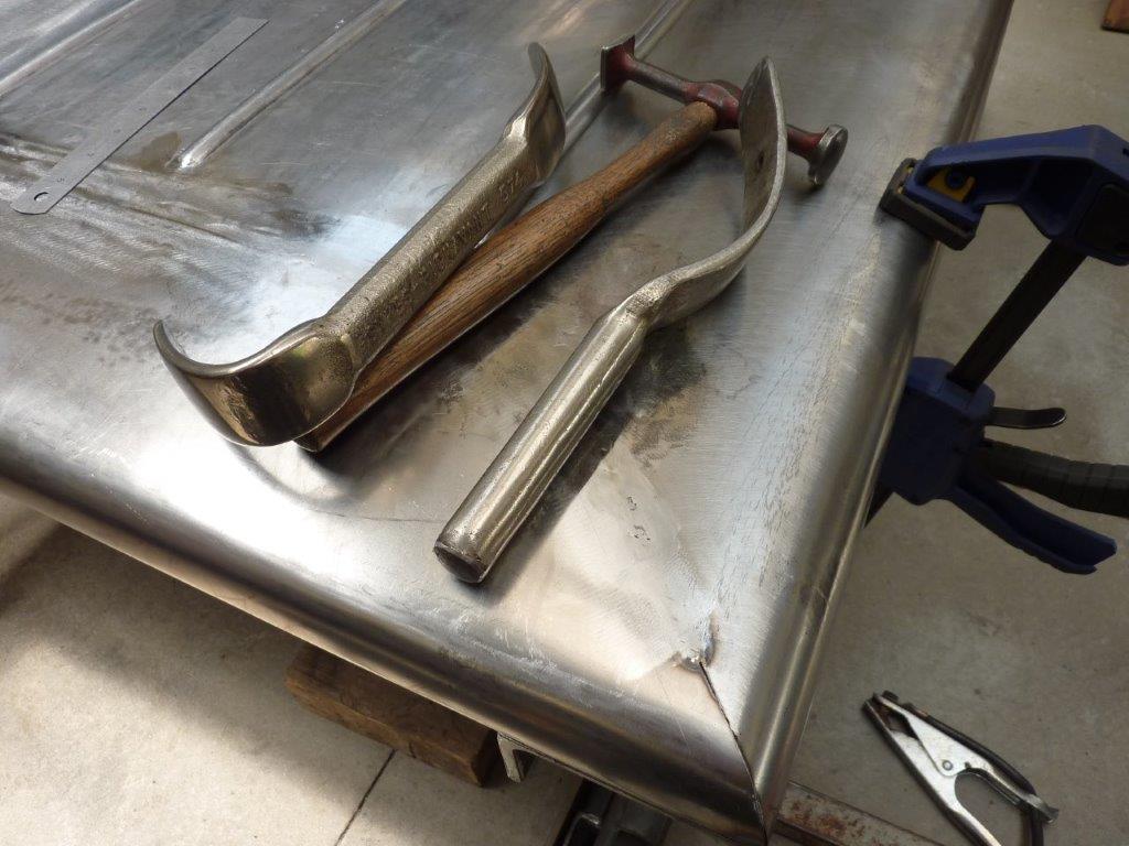
Couldn't use the same spoons as last time as was higher up in the radius. Shaped the end of the small one to do 95% of the work. No hitting from the underside as inside the frame area. Getting most of it our levering and tapping down the high spots at the same time.
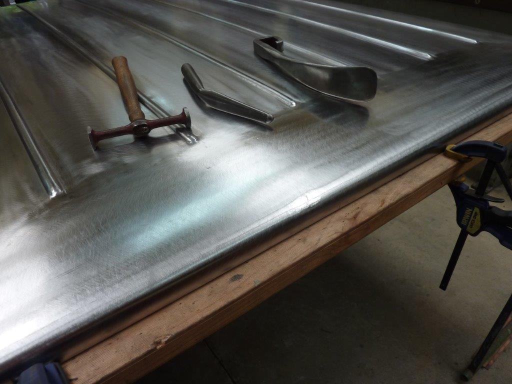
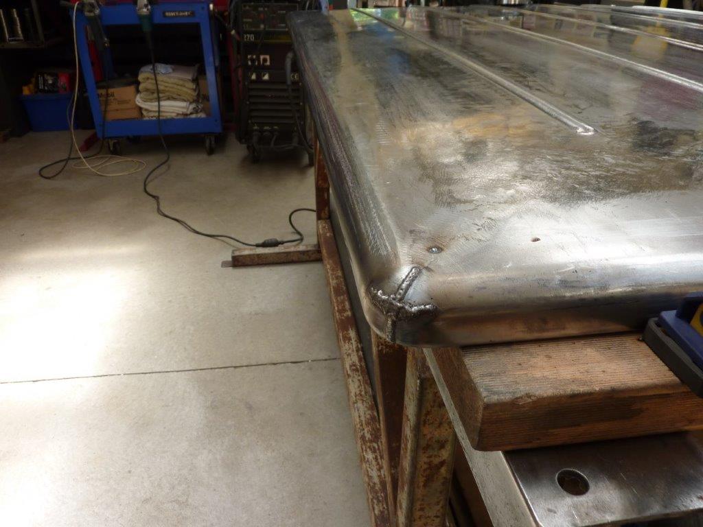
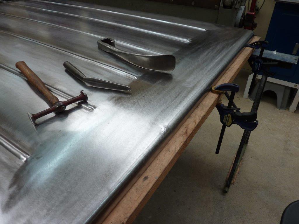
Almost there now and no filing, sanding done at all. Just the three tools above and taken about 30 minutes.
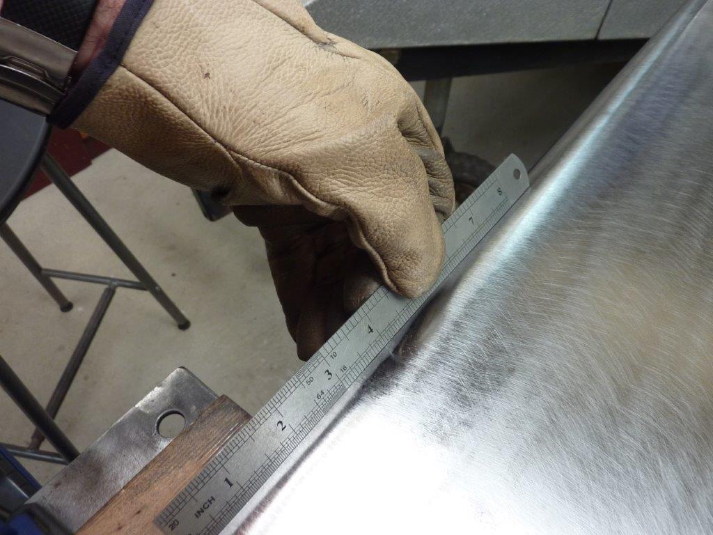
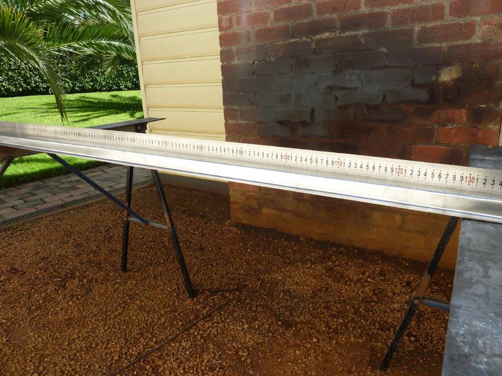
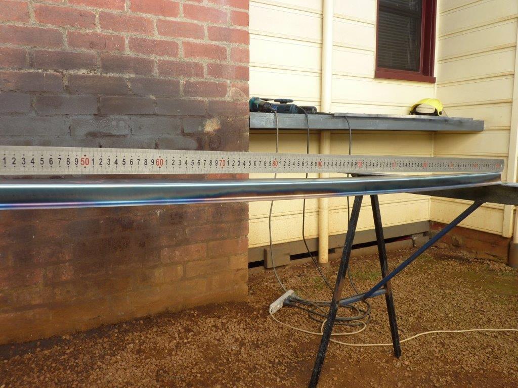
Got it raised and the polished area is just from the hammering and nothing else. The crease is right by the 4" mark.
There was a little bit of stretch from the impact so a quick pass over it with the shrinking disc and then a light sand and strip disc. Barely tell it ever happened.
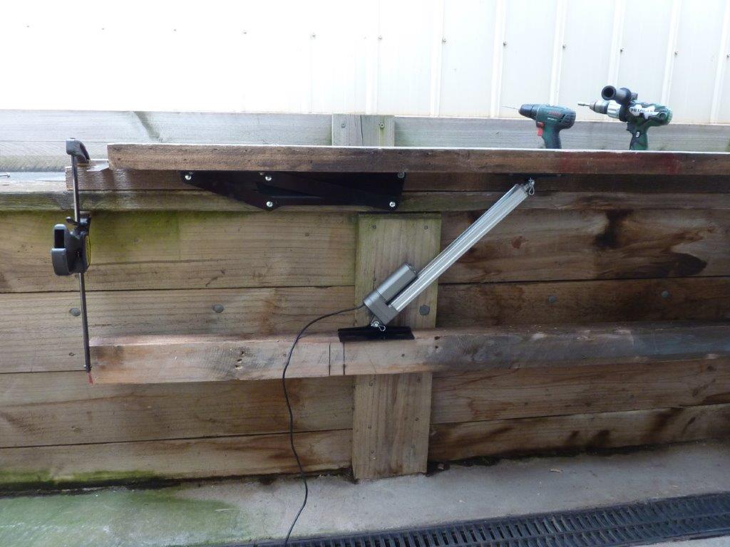
Well I had given up hope of using electric actuators to lift the cover as all I had seen were so slow! Then we saw a setup on a Ford XR6 Ute at the Sandown show we had taken the Truck too. Asked him if he could demonstrate it and it was so much faster! Not only that but had the hinges I had been looking for as well! So doing setup trials here to see how to mount the actuators and still get the lift angle we were after. Turns out this didn't work well as you used a lot of the travel as the hinge pivot moved forward with the actuator extending. So flipped it to work with the actuator base away from the hinge so the hinge pivot is getting closer to the actuator as it raises.
So now have plugged welded the hinge supports in as well as the actuator pivots.
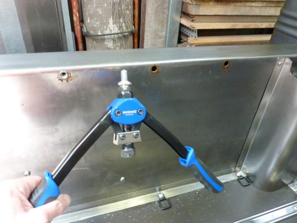
To attach the hinges to the bed sides I'm using 8mm Nutserts. Notice a good deal of wax to help stop rust in the hole and under the head.
I stepped the back of the hinge holes in for the Nutsert flange to sit in.
I have placed the hinge just back from the the fuel filler so I don't have to alter that.
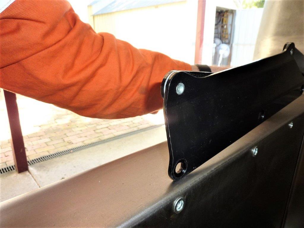
Can see here how it bolts up flush against the sides. This is the company I bought the hinges, actuators, remote controller and harness from: https://www.flat-top-products.com.au/
So using neoprene self adhesive seals to keep the water and dust out along with setting the same 4mm-5/32" gap I have for all my panels. Got the protective wax on too ready for fitment.
Marcus
To try where there is little hope, is to risk failure.
Not to try at all, is to guarantee it!
____| \______\
|/¯\ |¯ |----O||||O
()_)-o-)¯¯()_)-o-)_)
To try where there is little hope, is to risk failure.
Not to try at all, is to guarantee it!
____| \______\
|/¯\ |¯ |----O||||O
()_)-o-)¯¯()_)-o-)_)
-
Gojeep
- Old Hand
- Posts: 7221
- Joined: Mon Jan 07, 2008 1:24 pm
- Location: Eastern Suburbs of Melbourne
- Contact:
Re: Grand Willys Project
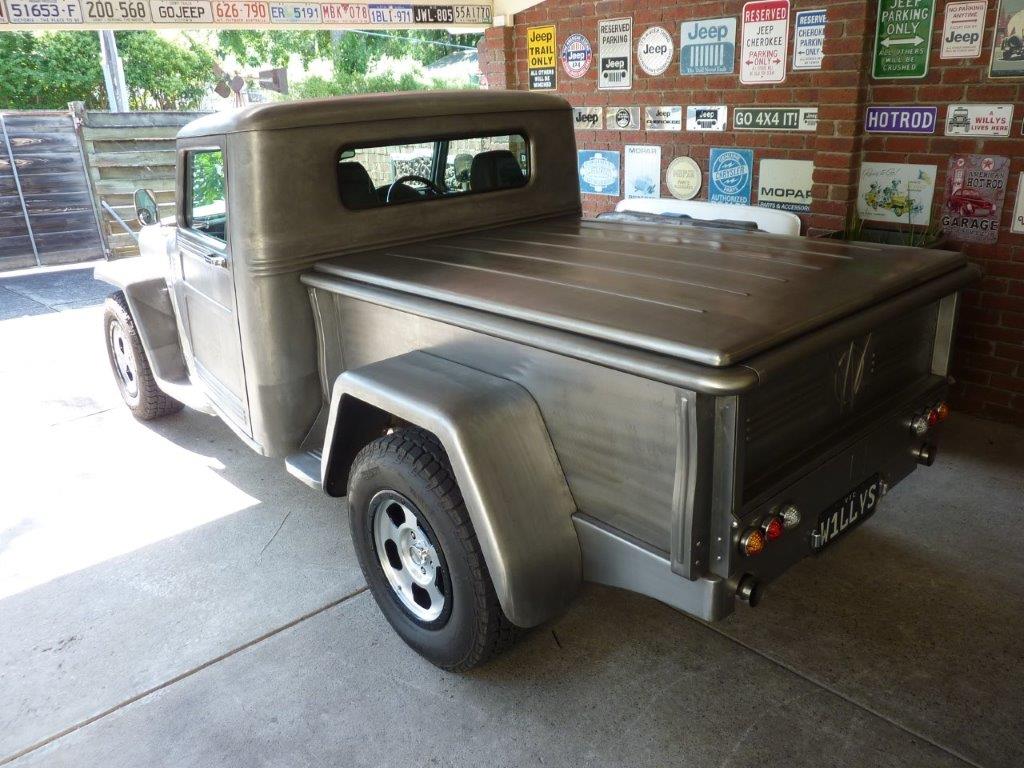
First time on there so finally get a chance to see what it looks like. Not once was the cover on until finished!
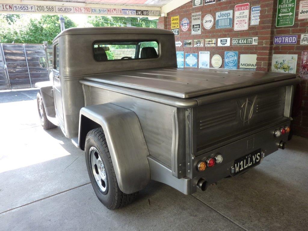
Very happy with the profile and it's everything I hoped it would be.
Now you can see too why I wanted the type of hinges I used. Look how easy it is to fill the tank and put things in and out at this end of the bed. Will build a custom box later to fit in there.
I used this calculator to see how the different angles changed the load requirements on the actuator. Linear Actuator Calculator | FIRGELLI Automations You enter the size of the box and lid angle and weight, (mine came out to 24.8kg-55lbs), and work out the position and capacity of the actuators. Basically the further from the hinge and the more vertical the actuator is mounted, the less force you need. If you had a fixed pivot, (which I don't), you can plot the exact spot to mount it.
As you can see, 40* is more than enough. What is great using actuators over gas struts is it is not trying to push it upwards, breaking the seal against the bed, when closed. I adjusted it to put some tension on holding the lid down before it shuts off. A drive on poor roads into the country showed it didn't bang or flutter at all at speed, so really pleased with the outcome. No lift handle or locks penetrating the skin are also needed for a better, cleaner and more waterproof result.
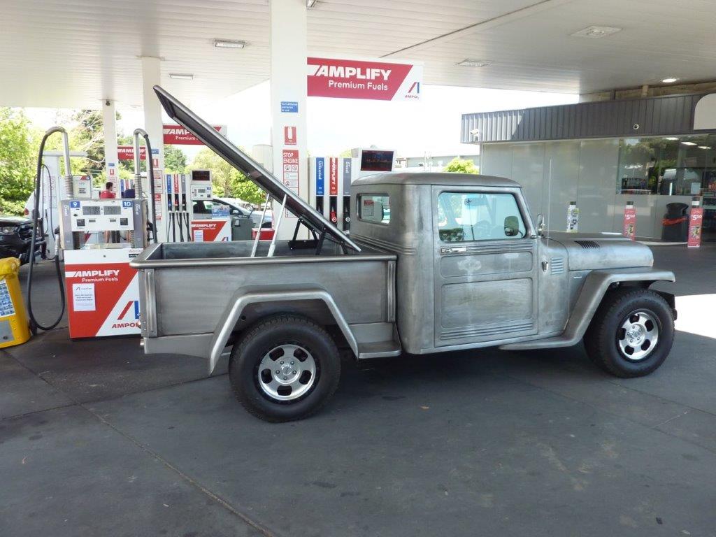
To fully raise it takes just 14 seconds and 10 seconds to go back down. Speed ratings are for unloaded and these came out at 45mm, (1.75") a second. Others I see are only between 3 and 8mm, (0.1-0.3") a second! So with 350mm of travel these have it would take over 2 minutes to raise it with the slower actuators.
I just took it to the service station to fill the tank and it is up before you get around to taking the cap off. You just let it go down as you walk off to pay.
Marcus
To try where there is little hope, is to risk failure.
Not to try at all, is to guarantee it!
____| \______\
|/¯\ |¯ |----O||||O
()_)-o-)¯¯()_)-o-)_)
To try where there is little hope, is to risk failure.
Not to try at all, is to guarantee it!
____| \______\
|/¯\ |¯ |----O||||O
()_)-o-)¯¯()_)-o-)_)
-
Gojeep
- Old Hand
- Posts: 7221
- Joined: Mon Jan 07, 2008 1:24 pm
- Location: Eastern Suburbs of Melbourne
- Contact:
Re: Grand Willys Project
Last modification of the year and maybe even the whole build! Thanks to all that have followed along with some even from the start over 10 years ago!
Happy new year to everyone and may next year be better than ever.
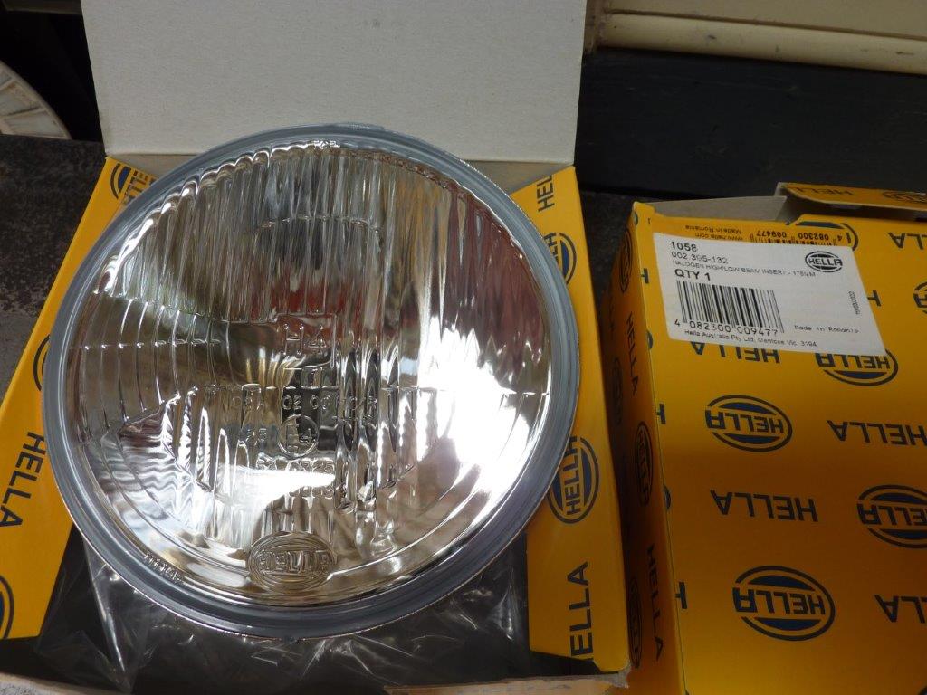
Last thing I wanted to change on the build is swap out the Narva LED headlight for some Hella H4 inserts. I fitted these same ones to my Hilux 40 years ago! #1058. The singe headed arrow means it is for left hand traffic, or RHD vehicles. I need this so it is approved for use on our roads. No arrow is for LHD's and double headed arrow is for either side. You can see the lens fluting is asymmetrical to make it dip to the shoulder of the road away from on coming drivers. https://www.hella.co.nz/en/about-us/tec ... binations/
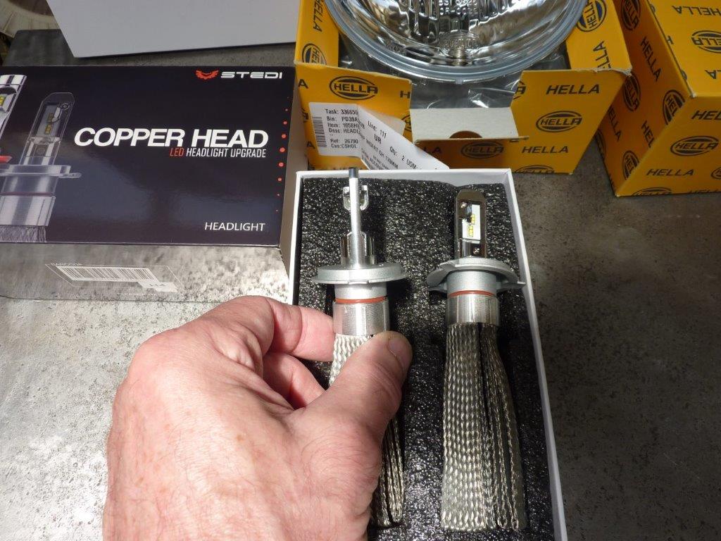
I have had good results fitting these particular LED replacement for halogen globes/bulbs in other vehicles including my Jeep Cherokee. They mimic the position of the halogen filament the best and even have the same chrome shroud over one set of them. https://www.stedi.com.au/copper-head-h4 ... n-kit.html
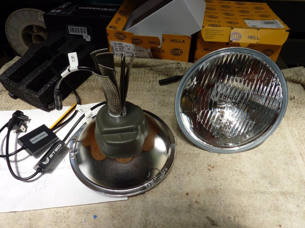
I was also able to still use the dust boot by feeding the cable, with the driver disconnected, through the hole before spreading out the heatsink braid.
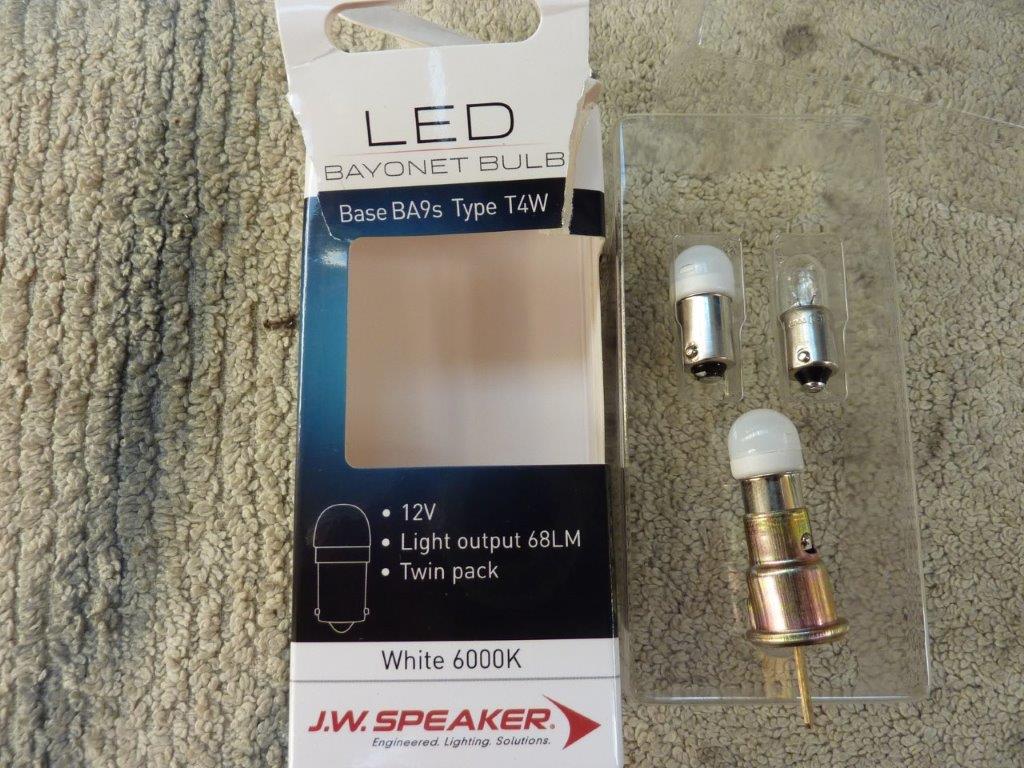
I also fitted a set of replacement LED's for the little parker/position light so they are nice and white too.
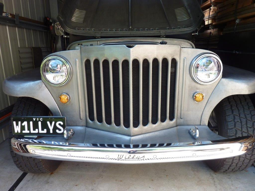
So here are the Narva headlights which look too modern in my eyes and clash with the rest of the body looking more period.
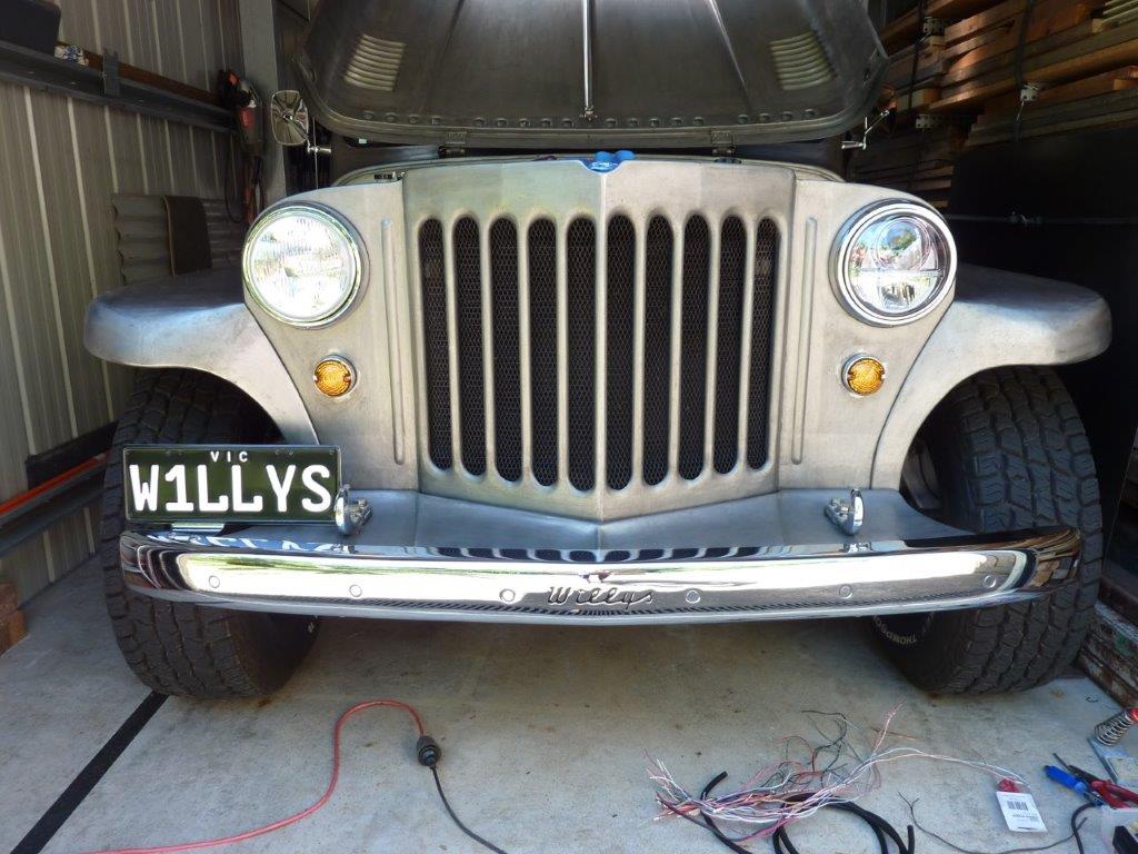
First new headlight fitted and can see the difference in the look.
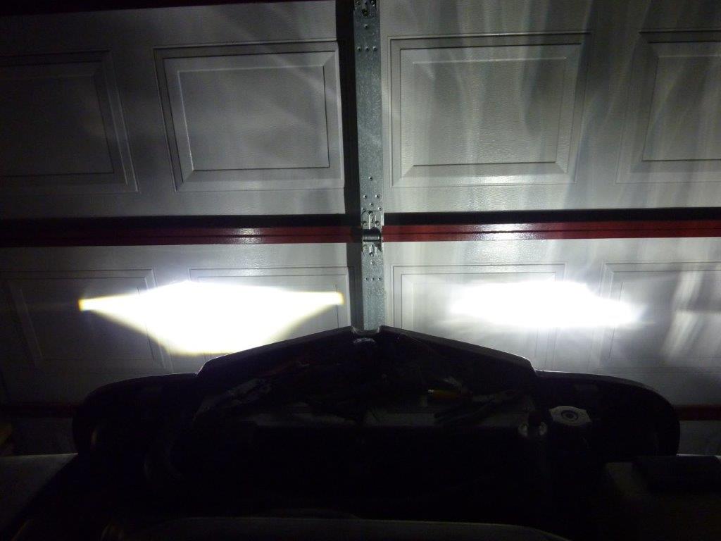
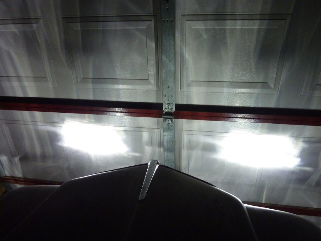
The beam pattern on the left is the Narva LED headlight and the right is the Hella with the Stedi LED globe/bulb fitted.
The biggest difference is that the high beam is actually higher and brighter than the Narva where there is little difference between high and low.
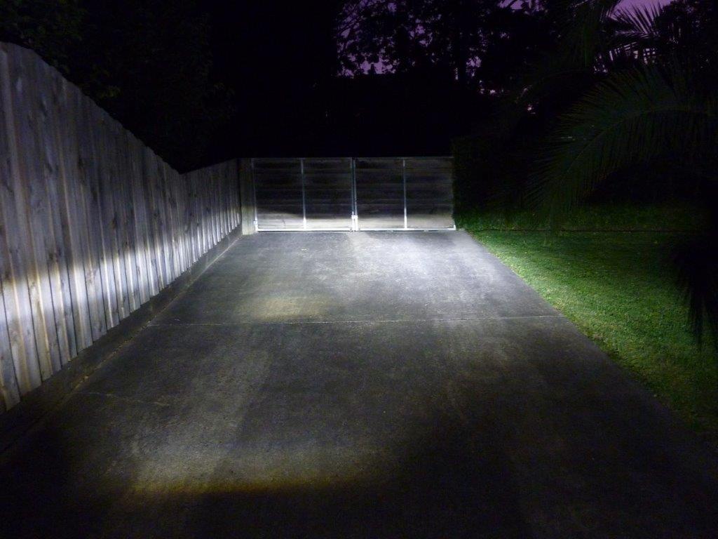
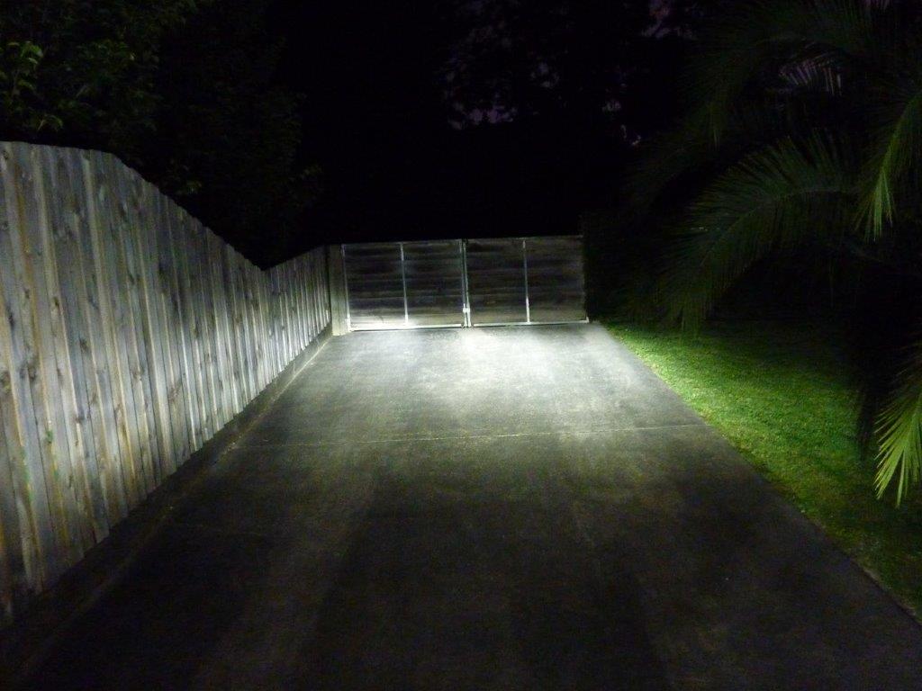
With the upslope to the drive it is harder to see but the Hella on the right, even on low beam, looks brighter with little stray light.
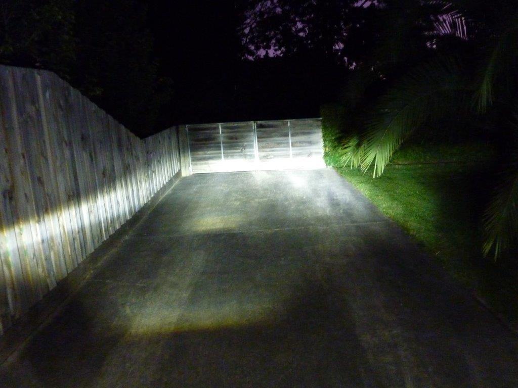
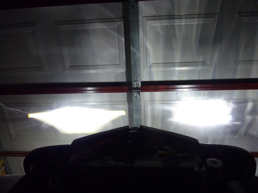
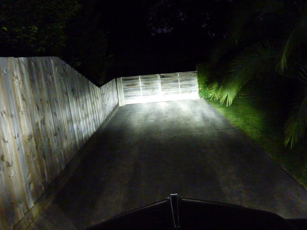
High beam with still the Narva on the left and the new Hella/Stedi combination on the right.
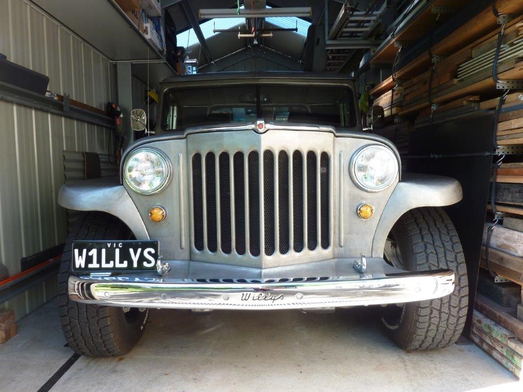
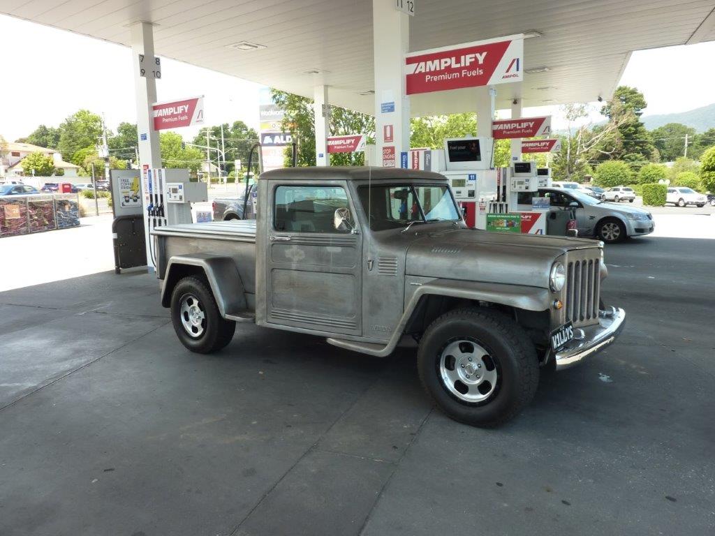
Both lights now changed and looking more in harmony with the rest of the outward appearance of the Willys.
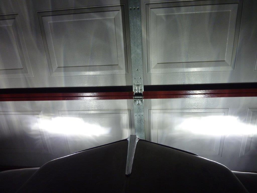
Both Hella/Stedi combination light patterns on low beam.
Both Hella/Stedi combination light patterns on high beam
Low beam still shows nice cut off and better light to the side.
High beam is higher and brighter. If I had a LHD I would have gone one of the Retrobright series LED headlamps. https://www.holley.com/products/electri ... trobright/
Happy new year to everyone and may next year be better than ever.
Last thing I wanted to change on the build is swap out the Narva LED headlight for some Hella H4 inserts. I fitted these same ones to my Hilux 40 years ago! #1058. The singe headed arrow means it is for left hand traffic, or RHD vehicles. I need this so it is approved for use on our roads. No arrow is for LHD's and double headed arrow is for either side. You can see the lens fluting is asymmetrical to make it dip to the shoulder of the road away from on coming drivers. https://www.hella.co.nz/en/about-us/tec ... binations/
I have had good results fitting these particular LED replacement for halogen globes/bulbs in other vehicles including my Jeep Cherokee. They mimic the position of the halogen filament the best and even have the same chrome shroud over one set of them. https://www.stedi.com.au/copper-head-h4 ... n-kit.html
I was also able to still use the dust boot by feeding the cable, with the driver disconnected, through the hole before spreading out the heatsink braid.
I also fitted a set of replacement LED's for the little parker/position light so they are nice and white too.
So here are the Narva headlights which look too modern in my eyes and clash with the rest of the body looking more period.
First new headlight fitted and can see the difference in the look.
The beam pattern on the left is the Narva LED headlight and the right is the Hella with the Stedi LED globe/bulb fitted.
The biggest difference is that the high beam is actually higher and brighter than the Narva where there is little difference between high and low.
With the upslope to the drive it is harder to see but the Hella on the right, even on low beam, looks brighter with little stray light.
High beam with still the Narva on the left and the new Hella/Stedi combination on the right.
Both lights now changed and looking more in harmony with the rest of the outward appearance of the Willys.
Both Hella/Stedi combination light patterns on low beam.
Both Hella/Stedi combination light patterns on high beam
Low beam still shows nice cut off and better light to the side.
High beam is higher and brighter. If I had a LHD I would have gone one of the Retrobright series LED headlamps. https://www.holley.com/products/electri ... trobright/
Marcus
To try where there is little hope, is to risk failure.
Not to try at all, is to guarantee it!
____| \______\
|/¯\ |¯ |----O||||O
()_)-o-)¯¯()_)-o-)_)
To try where there is little hope, is to risk failure.
Not to try at all, is to guarantee it!
____| \______\
|/¯\ |¯ |----O||||O
()_)-o-)¯¯()_)-o-)_)
-
Pato
- Posts: 103
- Joined: Thu Sep 23, 2010 2:12 am
- Location: Warrnambool
Re: Grand Willys Project
Thanks for the updates Marcus, its great to see the forum up and running again. Boy you must have been pissed off when you put the creases in the hard lid. I made 2 new running boards for my 35 Chev and I had a accident with my hoist resulting in damage similar to what you had on both running boards so I know the feeling. Cheers Pato
-
robtus

- Senior Member
- Posts: 1108
- Joined: Wed Apr 27, 2011 9:54 pm
- Location: Moffat Beach SUNNY QLD
- Contact:
Re: Grand Willys Project
Happy New Year Marcus and everyone !! Great to see the Forum up and running again. Also love what you have done with the bed cover Marcus, perfect as usual !!
I never make the same mistake twice, I do it 5 or 6 times just to be sure !!!
Making progress, https://www.muston.com/public_html/34%2 ... _Limo.html
Making progress, https://www.muston.com/public_html/34%2 ... _Limo.html
-
Gojeep
- Old Hand
- Posts: 7221
- Joined: Mon Jan 07, 2008 1:24 pm
- Location: Eastern Suburbs of Melbourne
- Contact:
Re: Grand Willys Project
Many thanks guys, it is good to be back and think this is the first forum I ever posted the build on too!
Marcus
To try where there is little hope, is to risk failure.
Not to try at all, is to guarantee it!
____| \______\
|/¯\ |¯ |----O||||O
()_)-o-)¯¯()_)-o-)_)
To try where there is little hope, is to risk failure.
Not to try at all, is to guarantee it!
____| \______\
|/¯\ |¯ |----O||||O
()_)-o-)¯¯()_)-o-)_)
-
NashRod
- Posts: 446
- Joined: Sat Dec 24, 2011 7:14 pm
- Location: Adelaide, SA
Re: Grand Willys Project
Thanks for the info on the lights Marcus, I've been wondering what's out there in the way of good head lights.
Happy New Year.
Chris
Happy New Year.
Chris